Describe the Boundary Box Use Case System
When drawing the use-case diagram an analyst should do the steps in this order. However this definition is too generic to describe the purpose as other four diagrams activity sequence collaboration and Statechart also have the same purpose.
Identifying Use Cases
Draw the use cases on the diagram identify the system boundary place the actors on the diagram and draw the lines connecting the actors to the use cases.

. Listed below are some important components of Use Case diagrams. A system boundary is an optional visual aid in the diagram. A use case diagram is a graphic depiction of the interactions among the elements of a system.
Spiders webmixed up 6. It is also referred to as scenario or functionality. Each boundary class is in turn a high-level representation of a window or similar construct in the user interface.
Each oval inside the system boundary box represents a use case. A usage scenario for a piece of software. Use Case Names Begin With a Strong Verb.
The system boundary is undefined or inconstant. A use case is a description of the functionality a specific usage of a system that a system provides. It does not add semantic value to the model.
We will look into some specific purpose which will distinguish it from other four diagrams. Include all critical components of a typical use case diagram. Anything within the box represents functionality that is in scope and anything outside the box is not.
It details a set of actions between actors and the data consumed and produced if any. It does not add semantic value to the model. The arrows on the use case diagram indicate which actors participate in each use case.
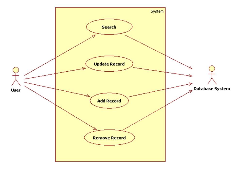
The optional system boundary helps to remind us that use cases are internal to the system and actors are external. In Figure 2 the arrow from the. Stick figures represent actors in the process and the actors participation in the system is modeled with a line between the actor and use case.
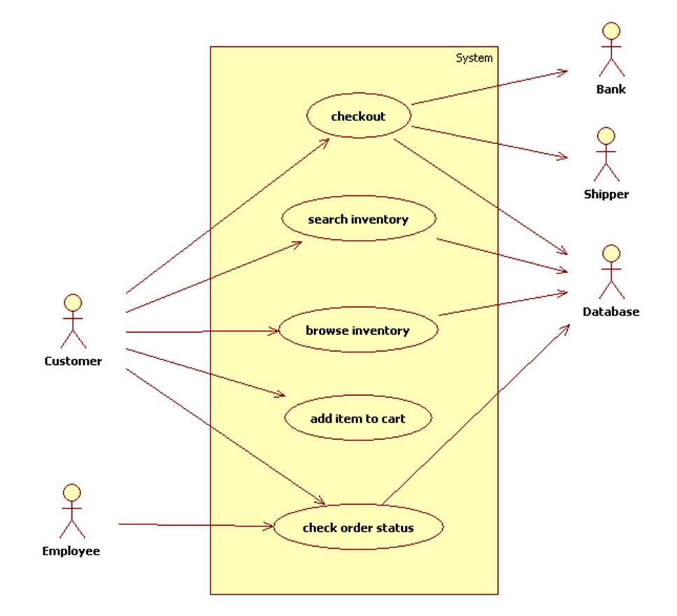
Draw stick figures to represent the actors of the system. Examples A Database Browser An E-Store Notice that we do not attempt to show structures like items or the cart nor the flow of control eg search items add items checkout then check status in a use case diagram. The use case diagram shows the interactions of the system with its users and some connections between internal system operations albeit at a high level of abstraction.
Draw a box to represent the system boundary. A use-case storyboard is described in terms of boundary classes and their static and dynamic relationships such as aggregations associations and links. A potential scenario in which a system receives an external request such as user input and responds to it.
System boundary depicted as a box surrounding the use cases with the lines between the actors and the use cases crossing the boundary as shown in figure. The diagram also allows a definition of the systems boundary. Often used in the plural to suggest situations where a piece of software may be useful.
O In creating your diagram be sure to do all of the following. How to Avoid Use-Case Pitfalls The Top 10 Use-Case Pitfalls 1. Identify the system boundary draw the use cases on the diagram place the actors on.
A use case is drawn as a horizontal ellipse on a UML use case diagram as you see in Figure 1. Describe how a use case interaction between user and system can be used to identify Entity Boundary and Controller classes in our design. The use cases which are the specific roles played by.
We review their content and use your feedback to keep the quality high. UML use case diagrams are ideal for. This convention of showing the system boundary in use case diagrams was used by Jacobsen 17 but does not.
The actor-to-use case relationships resemble a spiders web. This could be a person organization or an external system and usually drawn like skeleton shown below. A use case is a methodology used in system analysis to identify clarify and organize system requirements.
In software and systems engineering the phrase use case is a polyseme with two senses. Experts are tested by Chegg as specialists in their subject area. To depict the system boundary draw a box around the use case itself.
A system boundary is a rectangle that you can draw in a use-case diagram to separate the use cases that are internal to a system from the actors that are external to the system. Notation of System Boundary Subject is a rectangle with Systems name on top of the rectangle. Use cases are represented with a labeled oval shape.
This clearly separates the actors intention from the systems responsibility. The use cases are written from the systems not the actors point of view. The purpose of use case diagram is to capture the dynamic aspect of a system.
A system boundary is an optional visual aid in the diagram. Who are the experts. Describing the system by grouping the use cases in the rectangle boundary the System Boundary in Visual Paradigm provides use case containment behavior.
Actor in a use case diagram is any entity that performs a role in one given system. Extension Point Use Case Scheduling Use Case Details Textual Analysis System Boundary. O system boundary box named to describe the scope of the focal system o use cases their inclusion properly matches the story o use case names should be short yet clear as to their purpose begin with a verb o actors representing.
The actor names are inconsistent. A system boundary is a rectangle that you can draw in a use-case diagram to separate the use cases that are internal to a system from the actors that are external to the system. You can draw a rectangle around the use cases called the system boundary box to indicates the scope of your system.
A use case diagram UCD-A UCD defines the high-level features and functionality that the application system should include. The use case descriptions can exist in a textual form a simple table where the Use Case diagram provides additional information about the relationship between the use cases and the external users. A use case represents a function or an action within the system.
Place Your Primary Use Cases In The Top-Left Corner Of The. The benefits of this approach are the following. Specifying relationships in diagrams.
Although Figure 55 provides an example of a use case you can build one. There are too many use cases. A use case describes a sequence of actions that provide a measurable value to an actor.
Its drawn as an oval and named with the function. Name Use Cases Using Domain Terminology.
Identifying Use Cases

Pin On Manual Testing
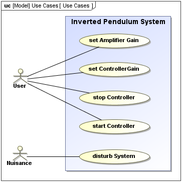
Sysml Use Case Diagram
0 Response to "Describe the Boundary Box Use Case System"
Post a Comment